The Duplexer
The duplexer is by far the most expensive part of a low power repeater and consumed almost 50% of my repeater budget. The duplexer allows both the transmit and receive radios to simultaneously use one antenna. It does this by placing three deep notch filters on top of the transmit and receive frequency to isolate the receive and transmit radios from one another. My repeater uses an RFS 633-6A-2N pass/reject triple notch filter duplexer. The notch filters prevent the transmit signal from getting into the receive radio, and keeps the receive signal from getting into the transmit radio. I bought a used Radio Frequency Systems (RFS but also sold as Celwave and Motorola) 633-6A-2N 50 watt UHF 450-470MHz duplexer on ebay (N=N connectors) for $480.
Signal Flow Through the Duplexer
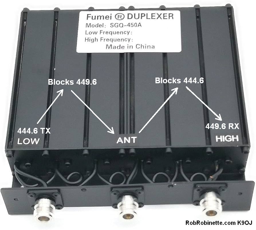
444.6MHz is the repeater transmit frequency, 449.6 is the receive frequency. The signal from the repeater transmitter enters at the left LOW connector, then has 449.6MHz filtered out by the three Low cavity notch filters. The signal then goes out the ANT connector to the repeater antenna. The transmit and receive signals come in from the ANT connector, has the 444.6MHz transmit signal filtered out by the High notch filters, then goes out to the repeater receiver through the HIGH connector. Note that the notch filters work in both directions.
The 633-6A-2N is a pass/reject notch filter duplexer but there are also more expensive band pass filter and band pass reject filter duplexers. Notch filter duplexers are not suitable for repeater sites with other transmitters because they only filter the transmitter they are tuned to, not other nearby transmitters. Use band pass or band pass reject duplexers at sites with multiple transmitters. Band pass reject duplexers are typically what you will find on crowded mountain top repeater sights. Band pass reject duplexers use both pass band pass and notch filters to remove all RF signals except the repeater transmit and receive frequencies. Note that I am using a small, 50 watt UHF duplexer. VHF duplexers are much larger due to wavelength and tight 0.6MHz repeater split. They are typically much more expensive than UHF duplexers. Hamventions are the best place to find good deals on duplexers and other repeater parts.
Large VHF Repeater Duplexer
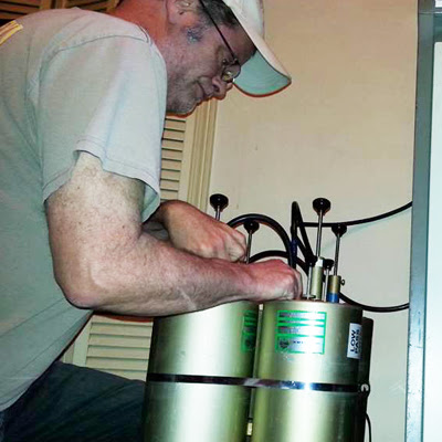
The large tube structures are mechanical resonant cavity filters. Rods with knobs are the cavity tuning adjusters and typically work by changing capacitance to tune the cavity resonant frequency.
You must pay attention to the duplexer's frequency band and minimum frequency split. My 633-6A duplexer is rated for 450-470MHz and 5MHz split (standard UHF repeater split) but it operates well at 444.6 & 449.6MHz. I do not recommend a duplexer that's rated for 470 and higher frequencies--that's just too far away from the Ham band.
50 Watt UHF Repeater Duplexer
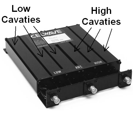
For my M17 UHF repeater I used an RFS/Celwave/Motorola 633-6A-2N UHF 50 watt notch filter duplexer. It has three tuned, resonant cavity notch filters for the transmit frequency, and three tuned, resonant cavity notch filters for the receive frequency. Each cavity creates a notch filter and three notch filters are stacked on top of the transmit and receive frequencies. Duplexers MUST be tuned to the repeater transmit and receive frequencies. The cavity tuning screws are on the other end of the duplexer. The 633-6A-2B model shown above has BNC connectors but the 633-6A-2N comes with N connectors.
Tuning a duplexer requires a service monitor, spectrum analyzer with a tracking generator, or VNA (Vector Network Analyzer). You can always ask your local ham club for help. Our local club has Bob Gass, a very knowledgeable, friendly, and helpful repeater expert that's willing to travel with his service monitor to tune repeater duplexers. You want to tune a duplexer at the repeater site, if possible, because altitude change and bumpy car rides can cause the mechanical duplexer filters to shift off frequency. After tuning, be sure and put a frequency label with the High and Low frequencies on it for future reference.
RIGOL and Siglent sell some nice, modern spectrum analyzers with tracking generators. The RIGOL DSA815-TG $999, Siglent SSA3021X Plus $1,650, and RIGOL RSA5032N $5,999, have tracking generators and can tune duplexers.
Siglent SSA3032X Plus Spectrum Analyzer + Tracking Generator
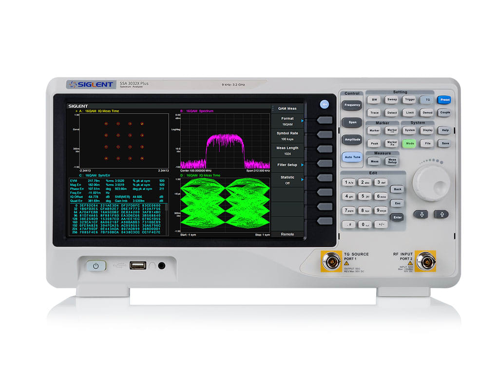
This is a sex machine parading about as a spectrum analyzer. The two N connectors at lower right are tracking generator output (left) and spectrum analyzer input (right). To tune a duplexer, the tracking generator output is connected to the duplexer ANT connector. The spectrum analyzer input is connected to the duplexer HIGH or LOW connector. The display above shows the analysis of a 16QAM digital signal with constellation, spectrum, symbol table and eye diagram. Available on Amazon, the $1650 SSA3021X can be cross-flashed to SSA3032X Plus (3.2GHz) or SVA1032X functionality which enables 3.2GHz operation (up from standard 2.1GHz), enable VNA (Vector Network Analyzer) with Smith charts, and enable all software options ($5400 value). Just Google "SSA3021X Plus hack".
IFR FM/AM - 1200S Service Monitor
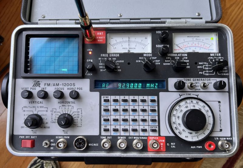
My 1988 IFR 1200S service monitor, shown above, combines a 250kHz-1GHz AM/FM/SSB FCC certified precision receiver and transmitter, spectrum analyzer, tracking generator, RF signal generator, audio tone generator, oscilloscope, and modulation and frequency error displays. It has everything you need to align, adjust and troubleshoot transceivers, repeaters and RF filters. Its tracking generator and spectrum analyzer are used to tune duplexers, filters, combiners, etc. The 1200S can be powered by 120 or 220v outlet, internal battery, or external 12v DC. The microphone connector is compatible with Regency CB 5-pin microphones (5 pins around central hole). Note: The IFR 1200A model does not come with a spectrum analyzer or tracking generator. The 1200S model comes with a spectrum analyzer but the tracking generator is optional. 1200S tracking generators can be found on ebay and are easy to install. I paid $1,900 for this newly factory refurbished and calibrated IFR 1200S from a local ham. See this short video for an example of a duplexer notch filter trace on the 1200S. The big difference between this service monitor and a spectrum analyzer + tracking generator (shown below), is the service monitor has an FCC approved, precision calibrated transmitter and receiver used to align and certify transmitters and receivers.
Tuning Duplexer With a Service Monitor
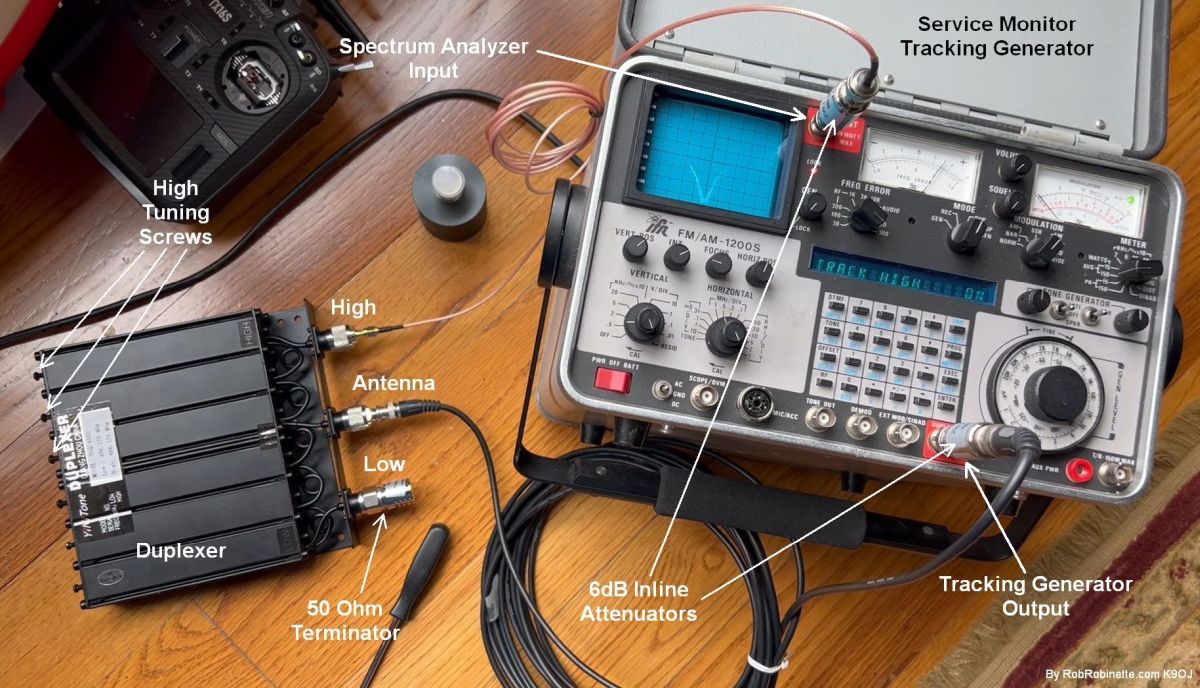
The service monitor's lower DUPLEX BNC connector is the tracking generator output. The upper ANT BNC connector is the spectrum analyzer input. You would connect a spectrum analyzer + tracking generator the same way as shown above. With the notch filter trace showing on the spectrum analyzer display, turn the three High cavity tuning screws to move the three notch traces to the repeater Low frequency. We then stack the three traces for a sharp, deep notch centered on the repeater Low frequency. The two optional inline 6dB attenuators shown above are acting as 50 ohm pass-through terminators to help keep the duplexer at 50 ohms impedance for more accurate tuning. Watch this short video showing a good duplexer notch filter trace on the 1200S service monitor.
We will use a service monitor or spectrum analyzer + tracking generator to tune the duplexer. The tracking generator supplies a swept radio signal that is sent through the duplexer while the spectrum analyzer shows the amount of RF signal that makes it through the duplexer.
First, set the Low repeater frequency in the service monitor. Then use the spectrum analyzer display to calibrate the display by centering the frequency spike on the display center reticule (this step is not required with modern spectrum analyzers). Zoom in using the HORIZONTAL control for a precise setting.
Next, connect the tracking generator output (DUPLEX BNC) to the duplexer Antenna connector (see photo above). To set the Low frequency notch, we connect to the duplexer High connector to the spectrum analyzer input (ANT BNC). We also need to put a 50ohm terminator on the unused Low duplexer connector (see photo above). I use two optional 6dB inline attenuators at the service monitor (see photo above) to keep the duplexer impedance at 50 ohms for more accurate tuning.
Set the spectrum analyzer bandwidth (HORIZONTAL) to 1MHz/DIV, set VERTICAL to anything other than OFF, and set MODE to DUP. Turn on the tracking generator with, "2ND FUNCT, 5/OPT" and set tracking to LOW, MED or HIGH with the keyboard up/down arrows for best signal trace. You will see one to three filter notches on the spectrum analyzer display.
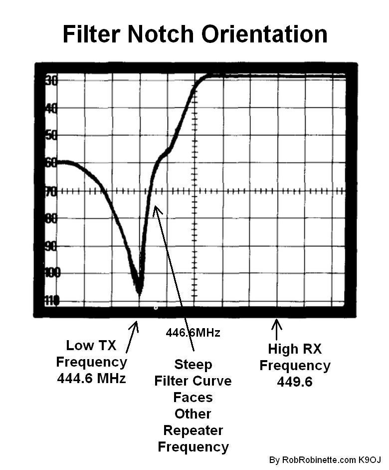
Tracking generator pass/reject notch trace showing 108dB of RF signal suppression at 444.6MHz. The repeater Low frequency is 444.6 and repeater high frequency is 449.6 (standard +5MHz split). The center frequency, 446.6MHz has been set as the display center frequency.
The reason duplexers are marked with "High" and "Low" inputs is so the orientation of the pass/reject notch filters is correct. "Pass/reject" means the notch filters are not symmetric. One side of the notch will attenuate, while the other side does not. The trace above shows that frequencies below our TX frequency of 444.6MHz will be suppressed by 60dB. The High filter notch will suppress frequencies above the 449.6MHz RX frequency, so we orient the transmit and receive notch filters so they attenuate unwanted signals beyond the repeater receive and transmit frequencies.
The above tracking generator trace shows the Low frequency filter notch. With correct orientation, as in the trace above, the steep side of the filter curve should be on the same side as the High repeater frequency. If incorrect (backward orientation), the notch shape will attenuate the other repeater frequency and not provide isolation. Note how the filter curve at 449.6 provides very little attenuation to the High receive frequency. For the High frequency filter notch, the trace would be reversed, with the steep side of the curve on the left, Low frequency side. To sum up, the steep side of the filter trace should face the other repeater frequency. This is why you should label your duplexer inputs "High" and "Low", not "TX" and "RX".
The RFS/Motorola UHF duplexer I used has six duplexer cavities that need to be adjusted. Three cavities for transmit, and three for receive. Adjust the three High cavity tuning screws to stack the three filter notches together over the repeater Low frequency. At this point we're looking to make the notch as deep and sharp as possible, centered on the repeater Low frequency. Reduce spectrum analyzer bandwidth to 10kHz for final tweaking. Lock down the cavity screw lock nuts and verify the notch still looks good.
Move the spectrum analyzer connection from the duplexer High connector to the duplexer Low connector. Move the 50ohm terminator from the duplexer Low connector to the High connector, and repeat the tuning procedure for the repeater High frequency notch.
There are inexpensive Chinese made UHF and VHF duplexers that need a large 10MHz frequency split that will not support standard Ham repeater frequency splits, such as 0.6MHz VHF and 5MHz UHF. Be wary of them because you will not get enough band reject to run standard Ham repeater frequencies at anything over 5 watts. You can use them for non-standard 10MHz repeater splits but those repeaters tend to be used less than repeaters with standard splits.
Siglent SVA1032X Spectrum Analyzer + Tracking Generator
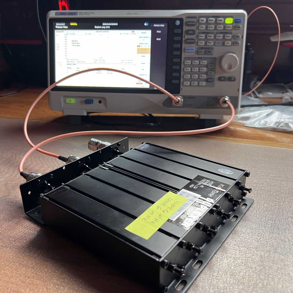
The tracking generator sends out a swept radio frequency signal to the duplexer that is filtered at 444.6 and 449.6MHz. The filtered signal flows out the HIGH connector to the spectrum analyzer and displays the duplexer frequency response. Note the 50 ohm terminator on the duplexer LOW connector and the six cavity filter tuning screws on the right. Spectrum analyzer screen capture shown below.
Chinese Duplexer Spectrum Graph
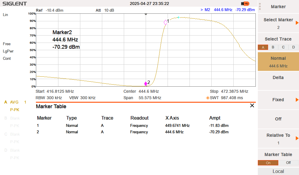
This $90 Chinese Fumei SGQ-450A duplexer is spec'd for 450-470MHz, 50 watts, and 5MHz spacing. Repeater transmit frequency of 444.6MHz is at Marker 2, receive frequency is 449.6 at Marker 1 (standard 5MHz split). You can see the receive frequency (Marker 1) is "down the slope" and showing more attenuation than wanted. A larger split of 9MHz would move the receive frequency to the right, near the small blue cross, for minimum attenuation. This duplexer should be spec'd at 10MHz minimum frequency split. Screen capture from Siglent SVA1032X spectrum analyzer.
Tuning a Duplexer With NanoVNA
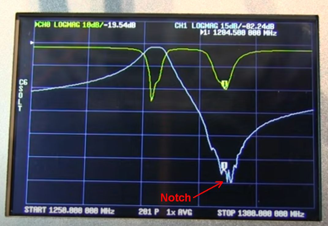
NanoVNA showing repeater High frequency of 1284.500MHz at "1" marker. Top right, CH1 shows -82.24dB of attenuation at the "1" marker. The blue line shows our filter notch trace. We adjust the three High frequency cavity tuning screws for the deepest, narrowest notch, centered on our repeater High frequency.
Tuning a notch filter duplexer with a NanoVNA: A service monitor is preferred here, but a NanoVNA does a surprisingly good job at tuning duplexers. Don't connect anything to the NanoVNA until you're finished with the calibration step. On the NanoVNA, select DISPLAY/TRACE and Turn off TRACE 2 and TRACE 3. Select FORMAT and ensure LOGMAG is checked. Then select DISPLAY/TRACE/TRACE 1 active then SCALE/DIV 15db. This will display S11 (CH0 horizontal scale 10db) and S21 (CH1 vertical scale 15db). Select STIMULUS and set Start & Stop frequencies to High repeater frequency. 449.6MHz is my repeater High frequency so I set START 449.100MHz and STOP 450.100MHz. Select CFG SWEEP/SWEEP POINTS to 201 points for high resolution.
Next calibrate the NanoVNA with CALIBRATE/RESET, CALIBRATE/OPEN, SHORT, LOAD, THRU, DONE, SAVE. Connect VNA transmit (CH1 lower SMA connector) to duplexer Antenna connector, VNA receive (CH0 upper SMA connector) to duplexer High connector, put 50ohm terminator on unused Low duplexer connector. Move VNA marker 1 to the repeater Low frequency. Yes, when we connect to the duplexer High connector, tune the low repeater frequency notch. When connected to the Low connector, tune the high repeater frequency.
The UHF duplexer I used (photo above) has six duplexer cavities, three for transmit, and three for receive. All six will need to be adjusted. Adjust the three High cavity tuning screws to stack the three filter notches together over the repeater Low frequency. At this point we're looking to make the notch as deep and sharp as possible, centered on the repeater Low frequency. Reduce the Start and Stop frequencies to 10kHz apart for final tweaking. Lock down the cavity screw lock nuts and verify the notch still looks good.
Next, do another calibration for the High frequency. Then adjust the notch by connecting the VNA transmit (CH1 lower SMA connector) to the duplexer Low connector, place the 50ohm terminator on the unused High duplex connector, move VNA marker 1 to the repeater high frequency and repeat the above procedure. See this video for more info on using a NanoVNA to tune a duplexer.